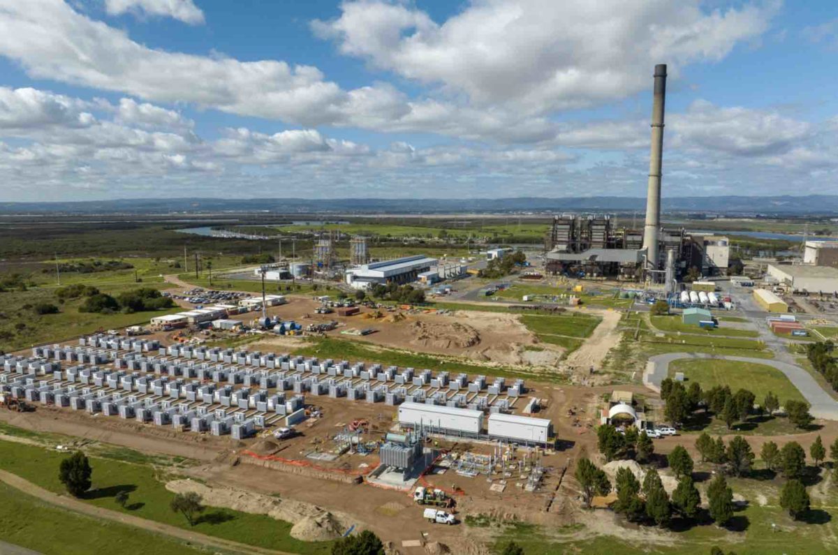
Until recently, practical applications of grid-forming (GFM) inverters were limited to micro and isolated grids and in smaller grid applications on the order of a few tens of megawatts.
Over the past 12 months, the landscape has changed rapidly, with more than 10 projects on the order of several hundred megawatts being developed worldwide for bulk power system applications.
However, this technology is not well understood when applied on a mega scale. This becomes more important moving forward, when it will possibly take over the role that synchronous generators have been performing for several decades as the workhorse of system stability support.
This blog post aims to provide a summary of GFM’s known capabilities, limitations, and considerations from a power system modelling and technical performance perspective, with a focus on grid interconnection studies and power system planning and operation.
Modelling and simulation
In addition to the conventional phasor-domain transient (PDT) modelling, electromagnetic transient (EMT) modelling is becoming increasingly important for power system dynamic analysis under scenarios with a high share of inverter-based resources (IBRs).
Both EMT and PDT models can be in the form of project-specific models (with site-specific control system parameters of the inverter) or generic models. Each of the EMT and PDT models, and, in turn, the project-specific and generic models, have certain applications and limitations justifying their complementary use in power system planning and operation and grid interconnection studies.
This holds true for both the grid-following inverters (GFL) and GFM inverters. This is because the control structure of both inverter types is very similar with different control objectives.
Common misunderstandings associated with the GFM modelling include:
– A view that PDT modelling has limited or no application for GFM since this technology is primarily intended for high IBR scenarios with very few or no synchronous generators online, leading to the obvious choice of EMT modelling.
– On the other side of the spectrum, a perception that since GFM IBRs usually emulate several characteristics of a synchronous machine, PDT modeling would be sufficient as it has always been for synchronous machines.
Experience to date indicates that EMT models provided by original equipment manufacturers (OEMs) for grid connection studies are often robust and accurate, and commonly a true representation of the actual inverter control code.
Various degrees of robustness and accuracy have been observed for PDT GFM models. This is because PDT model development requires the application of simplifying assumptions and manual development which takes longer to develop, tune, verify, and mature the model.
That said, PDT models of GFM from some OEMs offer comparable robustness and accuracy to the best project-specific models of GFL. Benchmarking of the EMT and PDT models will provide an opportunity to understand and address potential teething issues in the PDT models.
However, caution should be exercised, as PDT tools may not be inherently able to exhibit the same dynamic performance as that of an EMT model for all possible operating conditions, e.g., low system strength conditions.
The need for vendor-specific, project-specific models of GFM for grid interconnection studies is clear. This permits an accurate assessment of the positive contribution of this technology to the wider power system including the provision of sufficient system strength for stable operation of nearby GFL IBRs.
Furthermore, the use of the project-specific models will allow any potential adverse control system interactions with other GFM and GFL IBRs in the network to be assessed and addressed; GFM inverters are still able to interact with other inverters of similar control bandwidth.
Lastly, different OEMs have implemented different GFM control philosophies; at present, commercial products based on virtual synchronous generator/machine, droop, and synchronous power control can be found. Several combinations and permutations exist within each of these categories. As such, it is not prudent to use generic models for grid interconnection studies.
However, what’s best for grid interconnection studies differs from what’s best for long-term planning. Considering that rapid technology evolution can occur within the planning timeframe of several years, there is often uncertainty on the precise type and make of the generation to be connected in the future. This renders the use of site-specific, vendor-specific dynamic models impractical for long-term planning studies.
The use of the generic EMT and PDT models is therefore the most practical approach. Increasing uptake of IBR and the emergence of new instability phenomena worldwide means that EMT modelling will need to play a key role in addition to the commonly used PDT models.
Technical performance and practical experiences
IBRs, and in particular GFM, can be controlled in different ways and, unlike synchronous machines, have very few inherent characteristics. Notable differences between a GFM IBR and a synchronous machine include:
– Controllable and adjustable response of the GFM IBR as opposed to a fixed response from the synchronous machine. For example, the virtual inertia provided by a GFM IBR can be tailored to meet the needs of the power system to which it is connected, and can vary across a wide range.
– Unlike a synchronous machine where most capabilities are provided largely as inherent features without the opportunity to add or remove any, a GFM IBR can provide some or all of its possible grid-support capabilities depending on the system needs and the priority of the services required.
– Typically, a GFM IBR has a shorter construction and commissioning time, an important factor if the intended application is to increase the stability of GFL IBRs nearby.
Despite this flexibility, both the GFM and GFL IBRs are current-limited devices, which means that they cannot simultaneously provide optimal contribution towards multiple power system attributes.
Figure 1 shows how the total current available in the GFM can be allocated towards various grid-support services, with the aspects shown in green generally the default contributions which can also be provided by the GFL.
Correct prioritisation of these functions should be considered depending on the needs of the surrounding power system, recognizing that the highest possible contribution towards a certain attribute is not always the most desirable response. For example, practical experience indicates that provision of high inertia under low system strength conditions could adversely impact system voltages.

The increased uptake of GFM IBRs and the flexibility to provide multiple grid-support capabilities will mean that the overall power system and individual generator performance technical requirements are becoming increasingly intertwined.
Therefore, if a certain capability is sought from the GFM IBR, it is first important to determine what this capability is such that high-level functional requirements can be provided to the OEMs.
Furthermore, it is crucial to determine whether these capabilities are provided inherently at no additional cost of development or significant modifications of the original equipment are required to deliver the necessary system services.
For example, the provision of additional fault current will come at an extra cost, and the extent to which it will be required in the future power system with very little or no synchronous generation is not clear.
Suggested Focus Areas
The following are suggested focus areas for future development from the perspective of power system modelling and technical performance assessment:
– Improved EMT and PDT models of both the project-specific and generic GFM controls for use in power system planning and operation, and grid interconnection studies.
– Customised generator and power system technical standards accounting for differences between the GFL and GFM IBRs and synchronous machines, rather than adopting existing requirements developed primarily with synchronous machines and GFL IBRs in mind.
– More systematic processes for model acceptance testing, conformity assessment (including tuning), and model validation, recognising the highly interactive response of the GFM IBR with the wider power system.
– Forward-looking power system dynamic studies to determine future power system needs and the required generation mix. This includes answering the following questions:
- To what extent can GFM IBRs substitute for large centralised synchronous generators and how will system dynamics change, noting that often GFM IBRs are not installed in the same locations as the synchronous generators.
- What is the necessary mix of GFM and GFL IBRs as the power systems continue to evolve?
Babak Badrzadeh is technical director of power systems at Aurecon
This article is a contributed blog post from the Energy Systems Integration Group (ESIG). ESIG is a nonprofit organisation that marshals the expertise of the electricity industry’s technical community to support grid transformation and energy systems integration and operation. Additional information is available at https://www.esig.energy