This article is about the “unloved” part of the electrical system transition.
Most of the industry focus is on the sophisticated equipment that is being rolled out – the renewable energy resources (wind and solar) – the energy storage devices (batteries, hydro, compressed air etc.) – the sophisticated software – the substation assets.
But there is another component we should not overlook – the transmission system.
This is typically portrayed as a line on a drawing.
The representation as “just a line” affects people in subtle psychological ways. It gives people permission to overlook and dismiss this factor as being unimportant – of being easy to solve – being easy to model.
Hopefully by the end of this discussion, you will appreciate some of the subtleties hidden in the “line on a drawing” representation.
System strength is given a short definition which is used so that the industry can have a common understanding of what the concept is. It usually is framed as the ability of the system to maintain a steady state sinusoidal voltage waveform.
In this discussion – I will be avoiding this approach – not because of any explicit disagreement – but because I believe the relatively short definition lulls people into a similar state of mind that the “line on a drawing” encourages. I.e. it encourages modes of thought which act to encourage quick , easy and potentially completely wrong responses rather than more nuanced approaches.
Rather than using the vague term “system-strength” – this presentation will be about “emerging issues” that we (as an industry) will have to address as the transition proceeds.
The first step in any solution process is recognizing the issue.
We need to look beyond the “line on a drawing” or short definition of system strength.
In particular – system strength, as I believe we should understand the concept, is only obliquely related to system fault level.
The system strength rules currently in place in the NEM (and WEM) place emphasis on system fault level as a figure of merit.
High fault level is often considered roughly equivalent to high system strength.
This leads to projects being proposed to bolster fault level in the hope that this will also increase system strength.
I believe this is like bolstering the supports on a bridge without doing anything about the span. Your bridge might not fall down – but the weakness of the span will still limit how much traffic that can be carried.
This is a good moment to mention that I will be using a lot of metaphors to describe various concepts. I am doing this to try to reach as wide an audience as possible.
Obviously, the real Sydney Harbour bridge is not spanned using rope – but if it were – its ability to carry traffic would be severely curtailed. It would experience movement which would cause traffic to slow, its tensile strength would limit the number of vehicles it could support. With electrical transmission systems – the movement in the span is roughly analogous to voltage regulation across a transmission line, the tensile strength roughly analogous to line ratings.
Instead of thinking narrowly about system strength (whatever that is) – we should rather look at what the emerging issues we should be concerned about as the system transforms.
All of the new developments can cause significant commercial (as well as technical issues) – plant curtailment can be very significant resulting in serious loss of revenue.
Damage to plant and hazards to personnel have also occurred in some rare instances which can render plants and networks inoperable.
Network congestion due to thermal or voltage control constraints is a bit more subtle than most people’s intuition may lead them to think.
Braess’s paradox is an interesting example of how limits can change in surprising ways.
In certain examples – the transmission capability of a network can be improved by removing a connection.
To reiterate – the system strength has increased by deleting a transmission connection – which is contrary to most people’s intuition.
There are several You-tube videos on this subject if you want to delve into this further.
Where-ever we have very high voltage lines connected in parallel with lines of lower voltage – and points of interconnection (otherwise known as substations) – we have the requirements to enable Braess’s paradox situations to arise.
In practice – for other reasons (e.g. circuit reliability) – disconnecting short network pathways is rarely done – but it can and does occur in response to network faults and switching for maintenance, and the author is aware of one situation where this approach to improving network “horizontal” strength was implemented in practice.
Intuition is a poor guide where networks are concerned.
There is no substitute for calculation and modelling when considering constraints.
Many system blackouts have resulted because operators have made switching decisions based on intuition rather than prior analysis.
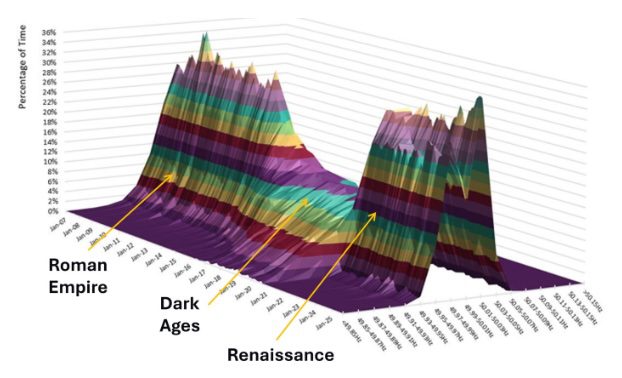
Histograms of NEM system frequency produced by AEMO – annotated by the author
As the transition proceeds and more mechanical rotating plant is supplanted by non-rotating power electronics – the system inertia will decrease. Some people worry this will cause issues with system frequency regulation – I am not one of those people.
Recent history has shown that governor control is far more important to controlling system frequency than inertia is.
In recent years we have experienced issues with poor frequency regulation which I have labelled “the dark ages” on the histograms above produced by AEMO – if the system frequency regulation had been allowed to continue to deteriorate this could have resulted in actual dark ages rather than being merely metaphorical.
I think it is fair to say that the poor frequency regulation in those years was the result of poor market design/behaviors and poor understanding of physics by various parties.
Fortunately, various engineers became alerted to this state of affairs and advocated for rule changes to bring the frequency back to a safer range of operation.
Specifically, Kate Summers , and Peter Sokolowski FAustMS FIEAust EngExec (amongst others) proposed and popularized rule changes which overlapped with similar proposals from AEMO. These tightened the frequency band via changes to generator governor deadbands and market reforms.
However, we should remain alert to the possibility that this issue may reemerge in the future because of some regulatory change that may get pushed through the system.
The increased penetration of inverter connected plant using grid following inverters if allowed to continue will cause a loss of the voltage reference. In the extreme – a system with 100% grid following inverters would follow each other and spiral out of control because the phase of the voltage waveform would be out of control.
As a metaphor – imagine group of blind people trying to collectively define a direction in which to walk – it would likely not end well.
A seeing eye dog can be likened to a grid forming (GFm) or traditional generator. It defines the direction that the Grid following (GFw) inverters can follow.
How many traditional generators or Grid forming inverters do we need for a system made up of Grid following inverters?
This is a bit like asking how many seeing eye dogs we need for a group of blind people. The usual ratio is one to one – but you could imagine 3 to one as shown in the image would probably work ok. Increase the ratio to 20 to one and it is clear this would be unmanageable.
Similar results occur for GFw and GFm inverters – there is no well-defined ratio we need to design for – but we know we should avoid too many plants with GFw inverters to minimize the risk of losing a well-defined voltage waveform.
Academic studies indicate 4-1 is probably the maximum safe ratio – but this varies with the impedance of the connecting transmission.
If the blind people in the picture were not holding hands but rather were holding each end of a length of elastic, you can see this would make life more difficult. They would have to walk more carefully and sense the tension in the length of elastic. In effect, the weakness of the connection would be compensated for by a well-tuned control system.
The behavior of the transmission system between installations is a key factor – not the fault level at the point of connection – although the two concepts are linked – it is important in detailed design not to confuse the two.
The “line on a drawing” image we all have of transmission systems can mislead us into thinking that they are like a well-maintained road – like the image on the right.
The following discussion will indicate why the more complicated and harder to negotiate road on the left may be the more appropriate image to come to mind.
Transient stability in power systems refers to the ability of a system to remain operational despite large disturbances. This is one situation where inertia (the guy on the left) has traditionally played an important role – but maybe that is about to change.
In particular – during faults – the ability of the transmission system to transmit power can be interrupted because the system voltage collapses to zero.
The metaphor I have chosen to describe this is a tug-a-war contest where the rope suddenly breaks. Transient stability is like the ability to maintain balance after the rope has broken (in power systems –the rope can sometimes magically repair itself in a fraction of a second) .
Machines with higher inertia experience lower acceleration and hence have improved ability to ride through disturbances.
However low or even zero inertia does not necessarily mean an installation can’t ride through a disturbance.
In particular, grid following inverters routinely ride through system faults even though they effectively have zero inertia – because they are effectively locked onto the voltage waveform via their phase locked loop (PLL) control systems.
In terms of system behavior; we should regard grid following vs grid forming not in pseudo-moral terms of ‘good’ and ‘evil’ or ‘evil’ and ‘good’ depending on your preference.
Rather we should view each technology as resources that can be used to keep the power system in control and resilient to various disturbances.
We need grid forming or traditional generation to provide a voltage phase reference – the seeing eye dogs using our previous metaphor.
But this does not mean we should throw out grid following inverters.
GFw inverters also have some desirable features – which are typically complementary to the properties of traditional and grid forming plant.
Specifically – they are effectively immune to “pole-slip” instabilities – and their lack of inertia (whether originating from mechanical or electronic sources) means they effectively do not contribute to power swing oscillations.
Machines with large inertia cause large power swings to occur after a disturbance – like a large mass on a spring. This can cause line protection to operate and has been known to result in cascade failures on power systems.
An optimal mix of Grid forming to Grid following devices would result in a more stable and resilient power system than we currently have now.
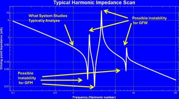
The “bumpy road metaphor” on one of the prior slides arises because of the fact that all transmission systems are subject to resonances at various frequencies.
This causes a profile of valleys and peaks as you traverse various frequencies – like pot-holes in a road.
Typical Impedance frequency behavior
This is the image we should have in mind when we think of transmission – not the straight-line motif we always see on drawings.
Grid following (GFw) inverters behave similarly to ideal current sources introduced in circuit theory. As such they push current into a power system even if it has high impedance which results in a high voltage pushback from the system.
As a result – GFw inverters are prone to control system oscillations if they encounter a high impedance peak.
By contrast – GFm inverters – which behave similarly to ideal voltage sources – have no control issues associated with high impedance peaks (in theory they can operate with the connection open – infinite impedance) – but they are susceptible to the low impedance valleys.
The nature of resonances means that for every high impedance peak – there is a corresponding low impedance valley.
Therefore – we can’t assume we won’t have similar oscillatory issues for traditional generation or grid forming inverters – we do – they just occur at different frequencies.
Currently the industry focus is on one frequency – the 50 Hz power transmission frequency.
We need to widen our focus if the transition is to proceed smoothly to include analysis across the full bandwidth.
Protection relays operate by measuring currents and voltages on the power system and detecting if the system is operating “normally” or it has developed a fault.
For traditional generators – the margin between normal operating current and voltages – and abnormal currents and voltages is large.
For inverter connected plant – the margin is reduced – which makes the design of protection systems a bit more challenging.
Current infeed from inverter plant to a power system – actual currents and voltages and sequence components
This situation is also exacerbated by designing inverter connected plant to respond to system voltage imbalances – something traditional generators can’t do.
What might have seemed like a good idea (by someone) to use inverters to balance the system – has the consequence of reducing fault current contributions to unbalanced faults – which makes setting overcurrent protection more challenging.
These are engineering issues which are easily solved via appropriate design – however – the first step towards good design is understanding how the plant actually behaves.
Power system engineers need to get up to date with how the new technologies behave.
Industry focus of current system strength rules is on the following areas:
System fault level – but discounting fault-level contributions from Grid following inverters.
I believe this is flawed accounting – the physical system does not distinguish between different sources of fault current.
Inertia – for poorly understood reasons a reduction in system inertia is considered to be “a problem”. In contrast I believe it should be considered “a parameter” amongst all the other parameters that affect the dynamic behavior of the system.
Low inertia systems actually have many advantages over higher inertia systems.
The current system strength rules have allocated a complicated and opaque system of financial penalties (for GFw inverters) to different points on the network – based on this approach. This seems to be trying to use non-physical market mechanisms to try to solve engineering problems associated with system strength – it was this sort of thinking that nearly resulted in catastrophe when the system frequency started to drift outside reasonable bounds.
I believe we should also be focusing on (when we talk about system strength) :
In my view – the industry seems to be concentrating on two key “system strength” concepts – namely fault level/SCR and inertia without fully understanding how they impact system behavior.
It’s a conservative reaction to change which lacks nuance.
So – low inertia must be ‘bad’ because its different from what we have had up until now.
Grid following must be ‘bad’ because traditional generation was always effectively grid forming (i.e. modelled conceptually as a voltage source).
Therefore, create some rules to counter the impact that new technologies are having on the grid.
This is having some deleterious effects on the network as the transition proceeds.
Specifically:
I believe we should try to embrace the actual complexity inherent in our power systems . We should not allow ourselves to be misled by the line on a drawing that we use to represent transmission systems.
Taking this complexity into account will ultimately result in the best and most economic outcome we can design.
Bruce Miller is principal consultant at PSC.
Incat founder Robert Clifford explains how a family-owned Tasmanian company built a ship many thought…
A company looking at hydrogen and graphite technologies among two low emission proposals for the…
The experience of decommissioning Australia's second-oldest wind farm proves that selling parts for re-use can…
Tech bros pushing SMRs are going to be "very angry" when they discover nuclear is…
Energy upgrades could deliver more than $100 billion in electricity bill savings to renters by…
Bowen says data centre demand could be key in getting struggling wind projects over line,…